Content
- Introduction
- The SD card
- Finding suitable IO points
- Finding ground
- Finding power, 3,3 volt
- Finding general IO output points
- Finding general IO input
- The wiring layout
- Implementing the modification
- Wiring points
- Setting up DD-WRT to support the modification
- Editing files and folders on the card
Introduction
This blog post guides you through adding a SD card interface to a Linksys WRT150N router. This guide is guild upon the SD/MMC Mod guide found on the dd-wrt web site.
Adding a SD card to your router enables more space to store logs/files or install additional programs and since a standard edition of the dd-wrt fills up most of the space available on the router it leaves only a little space for you to play around with. Since you with the SD card are able to increase the storage available to 1-2GB or more you can host a little FTP or WEB server.
As an alternative to doing this mod of the router is sharing a folder on your computer so it can be used by the router. This can be done through the Samba shares which is supported by dd-wrt this is the standard used by windows. (Samba works only over a wired line) The Samba Filesystem
The SD Card
If we take a look at the SD card we want to add to the router we can see that only a small amount of the SD pins is needed to control it.
| SD Pin |
SD function(SPI Mode) |
Direction |
| 1 |
Chip Select (CS) |
IN |
| 2 |
Data In (DI) |
IN |
| 3 |
Ground |
– |
| 4 |
Vcc (3.3v) |
– |
| 5 |
Clock (CLK) |
IN |
| 6 |
Ground |
– |
| 7 |
Data Out (DO) |
OUT |
| 8 |
Reserved |
– |
| 9 |
Reserved |
– |
The SD card
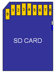
From this we can se that we need the following pins
- Ground
- Power 3,3 volt
- 2-3 output pins (We can just ground to Chip select, then we need the Clock and DI)
- 1 input pin (The data out from the SD card)
Finding suitable IO points
The SD card operate at 3,3 volt there fore wee first need to find a ground and Vcc connection point on the circuit board. When the SD card are powered up it needs some way of communicating with the rest of the router; we need to find at least 2 output pins and one input pin.
Finding ground
We need to find a grounded point this is very easy since it is present all over the PCB. Normally all metal housings are fore example connected to ground.
Finding power, 3,3 volt
Since the power supply on the router is 12 DC we can not use it directly we need another power source from the circuit board where we can measure 3,3 volt DC.
Finding general IO output points
Output means some way we can control the SD card. Here the LEDs are the most obvious choice. You can find out which LEDs are software controlled by loggin into the router by telnet or SSH and using the gpio command to test the IO ping from 0 to 9 looking for a LED shifting from on to off-on-off and so on.
- gpio enable <IO pin number> # to enable a IO pin, which switches the LED off
- gpio disable <IO pin number> # to disable a IO pin, which switches the LED on
- gpio poll <IO pin number> # to read the status of a switch
Here are a little script to make the pin switch between 0 and 1:
- while true; do gpio disable 1; sleep 3; gpio enable 1; sleep 3; done
Finding general IO input
To find an input pin use:
- gpio poll <IO pin number>
Then you will se a 00 or 01 when it goes on and off.
The wiring layout
Now the important part. I made the IO tests as described above and found the following:
| GPIO PIN |
Usage on WRT150N v1 |
| GPIO 0 |
– |
| GPIO 1 |
OUT: Power LED |
| GPIO 2 |
– |
| GPIO 3 |
OUT: Security LED Orange |
| GPIO 4 |
IN: Security Switch |
| GPIO 5 |
OUT: Security LED Green |
| GPIO 6 |
IO: Reset – don’t set this pin high your router will reset it self. |
| GPIO 7 |
– |
| GPIO 8 |
– |
| GPIO 9 |
– |
Here are how I decided to wire the SD card:
| SD Pin |
SD function(SPI Mode) |
Router IO |
Router PIN description |
Wire color |
| 1 |
Chip Select (CS) |
Ground |
|
Black |
| 2 |
Data In (DI) |
GPIO 5 |
Security LED Green |
Yellow |
| 3 |
Ground |
Ground |
|
Black |
| 4 |
Vcc (3.3v) |
Vcc 3,3 v |
|
Red |
| 5 |
Clock (CLK) |
GPIO 3 |
Security LED Orange |
Green |
| 6 |
Ground |
Ground |
|
Black |
| 7 |
Data Out (DO) |
GPIO 4 |
Security Switch |
White |
| 8 |
– |
– |
– |
– |
| 9 |
– |
– |
– |
– |
| |
|
|
|
|
Implementing the modification
Wiring points

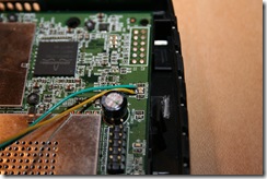
Remember to solder to on the negative side of the LED the other side is not lowered enough to change to logical zero.
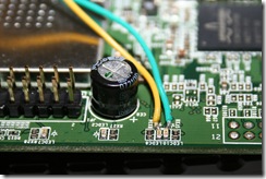
I tool the power and ground from JP2 (listed from right to left):
Now you have to solder the SD card to your print. I took a socket from an old USB 7 in 1 card reader.

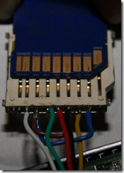

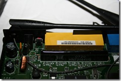
Here are some pictures of the soldering of my router


_thumb.jpg)
_thumb.jpg)
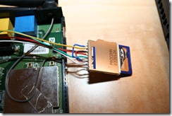
Now we have to get this new par (the SD card socket) fit nicely inside the plastic box.


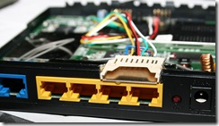
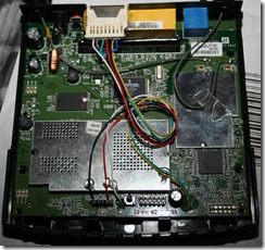


Setting up DD-WRT to support the modification
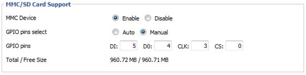
Now login to the dd-wrt web GUI and set the GPIO pins
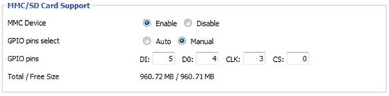
If you want to use the SD card for storing JFFS/IPKG then you have to mount it.
- Turn on jffs in the web admin
- Execute this command: mkdir /mmc/jffs
- Put this line in the startup script: –bind /mmc/jffs /jffs
The SD card will be formatted as EXT2 on startup so be patient it has to format it at first start. But you can see the interaction with the card on the LEDs.
Editing files and folders on the card
You can use WinSCP to access the cart from your computer. Remember to use SCP.
Installing packages on the router:
Guide
Preparing /jffs for /opt
- ~ # mkdir /jffs/opt
- ~ # mount -o bind /jffs/opt /opt
Installing ipkg-opt and uclibc-opt
Search PATH
- ~# export PATH=/opt/bin:/opt/sbin:$PATH
- unset LD_LIBRARY_PATH
Search
- ~ # /opt/bin/ipkg-opt list ‘*ftp*’
Source material
DD-WRT site
sd mmc mod.pdf (1.43 mb)
ipkg-opt.pdf (177.48 kb)







_2.jpg)
_2.jpg)


![NetstumblerToKML[1]](http://blog.lausdahl.com/wp-content/uploads/files_imported/WindowsLiveWriter/Wirelessnetworkdiscoveryandvisualization_116AC/NetstumblerToKML%5B1%5D_2.jpg)
![image_preview[2]](http://blog.lausdahl.com/wp-content/uploads/files_imported/WindowsLiveWriter/Wirelessnetworkdiscoveryandvisualization_116AC/image_preview%5B2%5D_2.jpg)
![chart-networks.preview[1]](http://blog.lausdahl.com/wp-content/uploads/files_imported/WindowsLiveWriter/Wirelessnetworkdiscoveryandvisualization_116AC/chart-networks.preview%5B1%5D_2.png)
![graph-timeline.preview[1]](http://blog.lausdahl.com/wp-content/uploads/files_imported/WindowsLiveWriter/Wirelessnetworkdiscoveryandvisualization_116AC/graph-timeline.preview%5B1%5D_2.png)